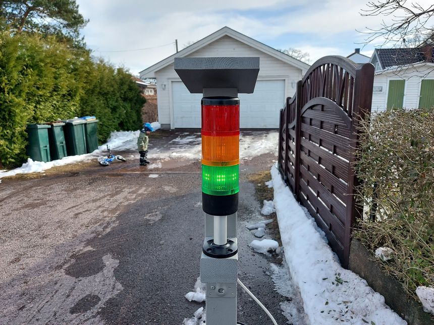
As the weather is warming up here in Norway — my kids have gotten their bikes out. To make it more fun, both for them and me, I figured I’d build a series of traffic signals that they could play with.
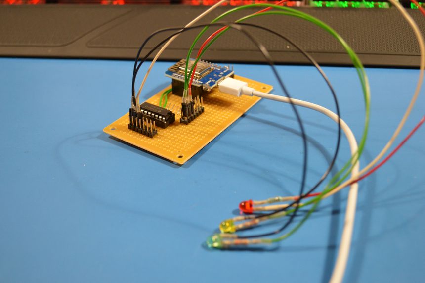
I first started with a traffic light, simple — red, yellow and green. To control it I am using a Raspberry Pi Zero W, this will allow me to make it communicate on Wi-Fi and MQTT later.